The User Defined reinforcement selection allows the user to select uniform reinforcement and RISAFloor ES will check that reinforcement. The program is using the maximum moments found in each FEA slab plate to check the referenced code.
Step 1: Define the Slab as a User Defined Slab when you create the floor.
Step 2: Determine how you want to define the Rebar.
Option 1: Use continuous reinforcement for both the top and bottom of the slab.
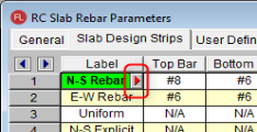
The Slab Design Rules will define the Top and Bottom rebar. See the Floors spreadsheet to define the Top Continuous.
Option 2: Use continuous bottom rebar only and on the top place rebar in regions over the columns and walls.
The Slab Design Rules will define the Top and Bottom rebar. The Columns and Walls spreadsheets allow you to define the regions.
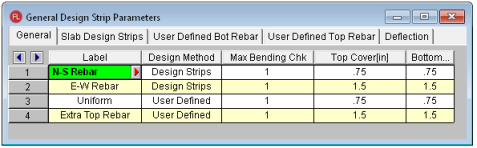
There are two methods available; Design Strips or User Defined. Design Strips use the traditional methods that use Column/Middle Strips and the User Defined allows the user to define a uniform rebar. When you select User Defined option the program will ignore Slab Design Strips tab.
Pressing the red arrow in the Label column will open the Design Rules Editor, where the spreadsheet information can be edited with an intuitive dialog.
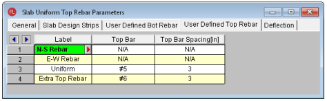
The General tab is used to enter all the cover spacing, bar size and spacing.
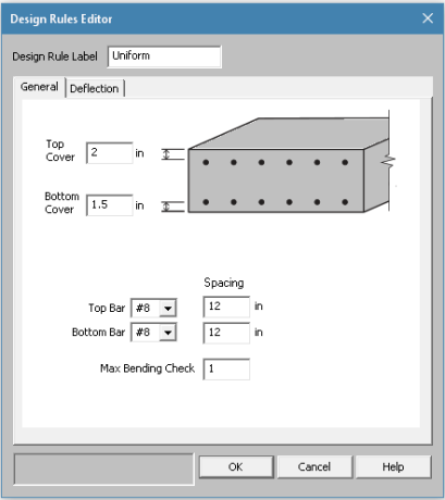
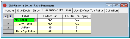
The Bottom Bar and Bottom Bar Spacing is continuous bottom rebar for both global directions.
There are two options for the Top Rebar; Continuous over the entire slab or over the supports (columns and walls).
In the Floors spreadsheet, you can select Continuous checkbox. This will apply continuous top rebar for both global directions based on the Top Rebar Design Rule.
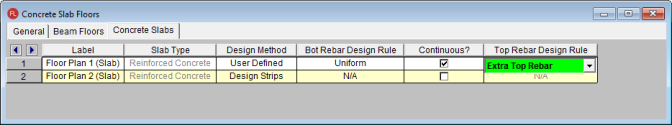
If the Continuous is not checked, the Top Rebar will only be placed over select regions over supports.
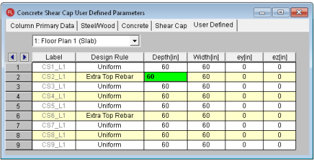
The Columns spreadsheet- User Defined tab allows you to customize the size of the rebar region over the column. The size will be determined by the Depth (X direction) and Width (Z direction). The top rebar region can also be moved eccentrically using ey and ez. The regions will automatically be trimmed at the edges of the slab.
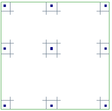
For example: this slab shows the top rebar regions only over the columns.
The Top Rebar will only be placed over select regions over supports. The Walls spreadsheet- User Defined tab allows you to customize the size of the rebar region over the walls. The size will be determined by the Depth (X direction) and Width (Z direction). The top rebar region can also be moved eccentrically using ey and ez. The regions will automatically be trimmed at the edges of the slab.
![]()
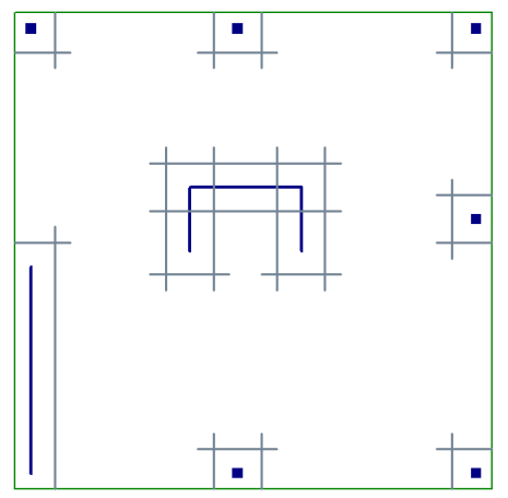
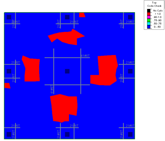
For example: this slab shows the top rebar regions only over the columns and walls.
If there is an area in the model that needs additional or different rebar than the default, you can define a special region that will replace the default top rebar. The User-Defined Rebar Region will replace all Top Rebar defined in that area with this new Top Rebar Design Rule. If it's on top of a column/wall, this Region will replace the Top Rebar defined in the column/wall regions.
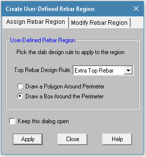
This can be accessed from the Graphical Editing Toolbar: 
The Top Rebar Design Rule can be selected from a drop-down list and then defined by drawing a polygon or box.
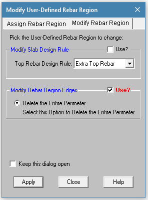
This can be used to change the User-Defined Rebar Region or Delete it.
Note: The User-Defined rebar regions will be displayed graphically as Top Rebar regions. They will replace the existing Top Rebar region only if it's fully encompassed.
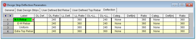
Although the Support Lines are not needed for design of the reinforcement using the User Defined methods, they are required for the Deflection to be calculated for the spans and cuts. For further information see the Deflection and Deflection Results Spreadsheet.
The program will use the Design Strip methodology to define the Design Strips. Therefore the Deflection criteria must be defined in the Design Rules defined as Design Strip. For example (above) N-S Rebar and E-W rebar will be used for Deflection criteria.
The User Defined Results are graphical. This allows you to see the Unity Check directly on model to see where it passes and fails.
After solution, click the User Defined Contours  to show the model with color coded Top and Bottom Unity Check.
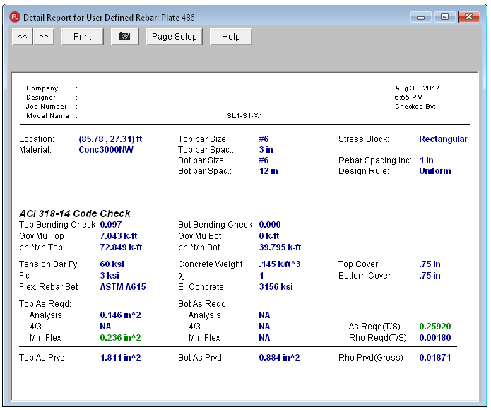
After solution, the Detail Report can be found by clicking on the Detail button  and then clicking anywhere on the slab.
The Detail Report for a User Defined floor is per plate. The Plate number is listed at the top including the Location of the plate. The forces are averaged per plate to provide a per foot check of reinforcement capacity vs demand. For further information, see the Rebar Design.
Note: